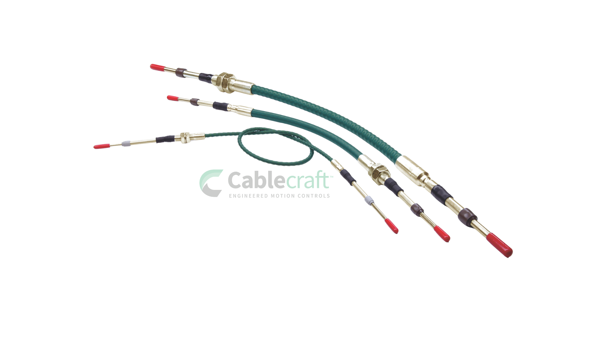
Description
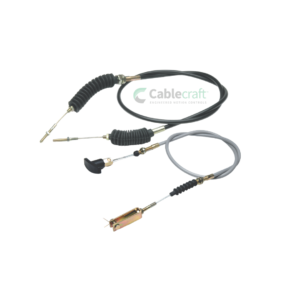
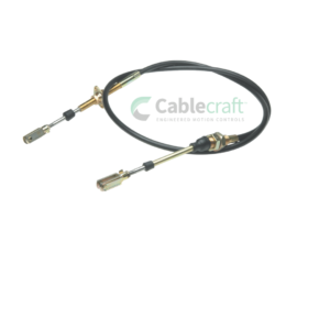
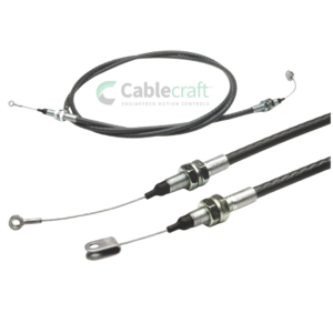
The Cablecraft Standard Push-Pull Control Cable Assembly provides a flexible and reliable way to transmit linear motion from one location to another. It can replace or simplify rigid rods, bellcranks, and mechanical linkages while allowing the control path to route around equipment structures and installation obstacles.
Standard Push-Pull Control Cable Overview
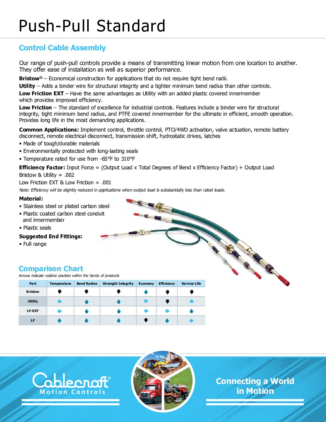
The product family includes multiple constructions for different combinations of economy, efficiency, routing, environmental resistance, and service life:
Bristow®
An economical construction for applications that do not require tight bend radii or the highest operating efficiency.
Utility
A rugged industrial control featuring binder-wire conduit construction for greater structural integrity and tighter bend-radius capability than basic economical controls.
Low Friction EXT
Combines the structural advantages of Utility construction with an extruded nylon-covered innermember for improved efficiency and smoother operation.
Low Friction
The premium standard industrial construction. It uses binder-wire conduit and a bonded PTFE-covered innermember for efficient, smooth operation, tighter routing, and long service life in demanding applications.
The family is environmentally protected with long-lasting seals and is documented for operation from -65°F to 310°F, depending on the selected construction and application.
| Construction | Best Suited For | Primary Advantage |
|---|---|---|
| Bristow® | Economical, simple routing | Lower-cost general-purpose construction |
| Utility | Rugged industrial equipment | Binder wire improves structural integrity |
| Low Friction EXT | Applications requiring improved efficiency | Nylon-covered innermember |
| Low Friction | Demanding, high-efficiency applications | PTFE-covered innermember and smooth operation |
Request a quote for Control Cables
Key Features and Benefits
- Transfers motion in both push and pull directions
- Four construction levels for different performance and cost requirements
- Available in very light, light, medium, and heavy-duty sizes
- Custom travel from 1 to 6 inches
- Custom overall cable length
- Threaded and grooved conduit-cap options
- Imperial and metric end rod threads
- Stainless steel material options
- Optional stainless steel support tubes and innermember armor
- Optional all-stainless exposed components
- Long-lasting environmental seals
- Optional enhanced wiper seal
- Full range of end-fitting options
- Suitable for OEM and replacement applications
- Custom configured during manufacture
Common Applications
- Implement controls
- Throttle controls
- Power take-off activation
- Four-wheel-drive activation
- Hydraulic and mechanical valve actuation
- Remote battery disconnects
- Remote electrical disconnects
- Transmission shift systems
- Hydrostatic drives
- Latches
- Choke controls
- Equipment engagement systems
- Construction equipment
- Agricultural equipment
- Heavy trucks
- Lawn and garden equipment
- Industrial machinery
- Specialty vehicles
Technical Specifications’
| Specification | Standard Push-Pull Family |
|---|---|
| Control Type | Flexible push-pull control cable |
| Motion Direction | Push and pull |
| Construction Options | Bristow, Utility, Low Friction EXT, Low Friction |
| Duty Sizes | Very light, light, medium, heavy |
| Travel | 1 to 6 inches |
| Operating Temperature | -65°F to 310°F |
| Conduit Ends | Threaded, grooved, or mixed |
| End Rod Threads | Imperial or metric |
| Standard Materials | Stainless steel or plated carbon steel |
| Conduit and Innermember | Plastic-coated carbon steel options |
| Seals | Plastic seals |
| End Fittings | Full range |
| Overall Length | Custom configured |
| Purchase Method | Request a quote |
Duty Sizes and End Rod Threads
| Duty Size | Code | UNF End Rod Thread | Metric Conversion |
|---|---|---|---|
| Very Light Duty | V | 10-32 UNF | M5 x 0.8 |
| Light Duty | L | 1/4-28 UNF | M6 x 1.0 |
| Medium Duty | M | 5/16-24 UNF | M8 x 1.25 |
| Heavy Duty | H | 3/8-24 UNF | M10 x 1.5 |
The correct size should be selected based on push load, pull load, travel, routing, bends, safety factor, and application environment.
Working Load by Duty Size
Working load is expressed below as push load / pull load. Push capacity decreases as travel increases, while the documented pull capacity remains constant within each duty family.
| Duty Size | At 1-Inch Travel | At 3-Inch Travel | At 6-Inch Travel |
|---|---|---|---|
| Very Light Duty | 80 / 120 lb | 70 / 120 lb | 30 / 120 lb |
| Light Duty | 150 / 230 lb | 125 / 230 lb | 50 / 230 lb |
| Medium Duty | 250 / 400 lb | 210 / 400 lb | 100 / 400 lb |
| Heavy Duty | 700 / 1,000 lb | 600 / 1,000 lb | 300 / 1,000 lb |
Maximum Input Overload
The legacy specification also provides maximum input overload values, expressed as push / pull.
| Duty Size | At 1-Inch Travel | At 3-Inch Travel | At 6-Inch Travel |
|---|---|---|---|
| Very Light Duty | 120 / 180 lb | 110 / 180 lb | 45 / 180 lb |
| Light Duty | 230 / 350 lb | 190 / 350 lb | 75 / 350 lb |
| Medium Duty | 400 / 600 lb | 300 / 600 lb | 150 / 600 lb |
| Heavy Duty | 1,000 / 1,500 lb | 900 / 1,500 lb | 450 / 1,500 lb |
Maximum overload is not a continuous working-load rating.
Bend Radius by Cable Size
| Duty Size | Cablecraft Minimum Bend Radius | Bristow Minimum Bend Radius |
|---|---|---|
| Very Light Duty | 2 inches | 5 inches |
| Light Duty | 3 inches | 7 inches |
| Medium Duty | 5 inches | 9 inches |
| Heavy Duty | 6 inches | Confirm availability |
Tighter bends, additional bends, and complex routing increase operating force and can affect efficiency, backlash, and service life.
Efficiency and Input Force
The legacy design guide uses the following calculation:
Input Force = (Output Load × Total Degrees of Bend × Efficiency Factor) + Output Load
Published efficiency factors are:
- Bristow and Utility: 0.002
- Low Friction EXT and Low Friction: 0.001
This means Low Friction EXT and Low Friction constructions generally require less additional input force through a routed cable path than Bristow or Utility.
Actual efficiency can vary with cable length, load, routing, bend radius, temperature, and condition.
Backlash Factors
| Duty Size | Backlash Factor per Degree of Bend |
|---|---|
| Very Light Duty | 0.00015 |
| Light Duty | 0.00020 |
| Medium Duty | 0.00025 |
| Heavy Duty | 0.00030 |
These values can help estimate lost motion created by bends in the installed cable path. Final system performance should be verified in the actual application.
Material and Corrosion-Resistance Options
Utility Series
| Legacy Series | Material Configuration |
|---|---|
| 173 | Stainless steel end rods |
| 174 | Stainless steel support tubes, end rods, and innermember armor |
| 175 | All exposed fittings and parts stainless steel, plus stainless innermember armor |
Low Friction EXT Series
| Legacy Series | Material Configuration |
|---|---|
| 313 | Stainless steel end rods |
| 314 | Stainless steel support tubes and end rods |
| 315 | All exposed fittings and parts stainless steel |
Low Friction Series
| Legacy Series | Material Configuration |
|---|---|
| 183 | Stainless steel end rods |
| 184 | Stainless steel support tubes and end rods |
| 185 | All exposed fittings and parts stainless steel |
Current series and material availability should be confirmed during quoting.
Conduit-End Configurations
Each end of the cable can use a threaded or grooved conduit cap.
| Code | Configuration |
|---|---|
| TT | Threaded to threaded |
| TG | Threaded to grooved |
| GG | Grooved to grooved |
The left and right mounting requirements should be identified separately to ensure the assembly fits the equipment.
Optional Features
Legacy order-code suffixes include:
| Code | Optional Feature |
|---|---|
| N | Two end rod jam nuts |
| W | Extra shake-proof washers on conduit ends |
| A | Combination of jam nuts and washers |
| P | Stamp with customer part number |
| S | Stamp with Cablecraft and customer part number |
| M | Metric end rod conversion |
An optional Model 6 wiper seal is also identified for applications requiring additional sealing.
These options should be confirmed before being shown as currently available.
FAQ’s
What is a standard push-pull control cable?
A standard push-pull control cable is a flexible mechanical assembly that transfers linear motion in both tension and compression. It can remotely operate throttles, valves, PTO systems, shifters, disconnects, latches, and other mechanisms.
What cable constructions are available?
The family includes Bristow, Utility, Low Friction EXT, and Low Friction constructions. They provide different levels of economy, structural integrity, efficiency, bend-radius capability, and service life.
What is the difference between Low Friction EXT and Low Friction?
Low Friction EXT uses an extruded nylon-covered innermember. Low Friction uses a bonded PTFE-covered innermember for highly efficient and smooth operation.
What duty sizes are available?
Sizes include very light, light, medium, and heavy duty, with end rod threads ranging from 10-32 UNF through 3/8-24 UNF.
Are metric threads available?
Yes. Metric conversions include M5, M6, M8, and M10 end rod threads.
What travel is available?
The product family supports travel from 1 to 6 inches in one-inch increments.
What is the operating temperature range?
The published family temperature range is -65°F to 310°F. Suitability should be confirmed for the selected cable construction.
Can both ends use different mounting styles?
Yes. Threaded and grooved conduit caps can be combined to suit different mounting arrangements on opposite ends.
Are stainless steel configurations available?
Yes. Depending on the series, options include stainless steel end rods, support tubes, innermember armor, or all exposed stainless steel components.
How do I select the correct duty size?
Select the duty size based on required push and pull loads, travel, routing, bends, safety factor, environment, and connection requirements.
Can Cablecraft build a custom length?
Yes. Overall length, travel, conduit ends, threads, seals, materials, and end fittings can be configured during manufacture.
Can this replace an existing push-pull cable?
It may be evaluated as a replacement candidate when length, travel, loads, routing, bend radius, threads, conduit mounts, and end fittings are confirmed.
What information is required for a quote?
Provide the application, push and pull loads, travel, overall length, bends, mounting styles, threads, fittings, material requirements, environmental exposure, quantity, and any available drawings or photos.